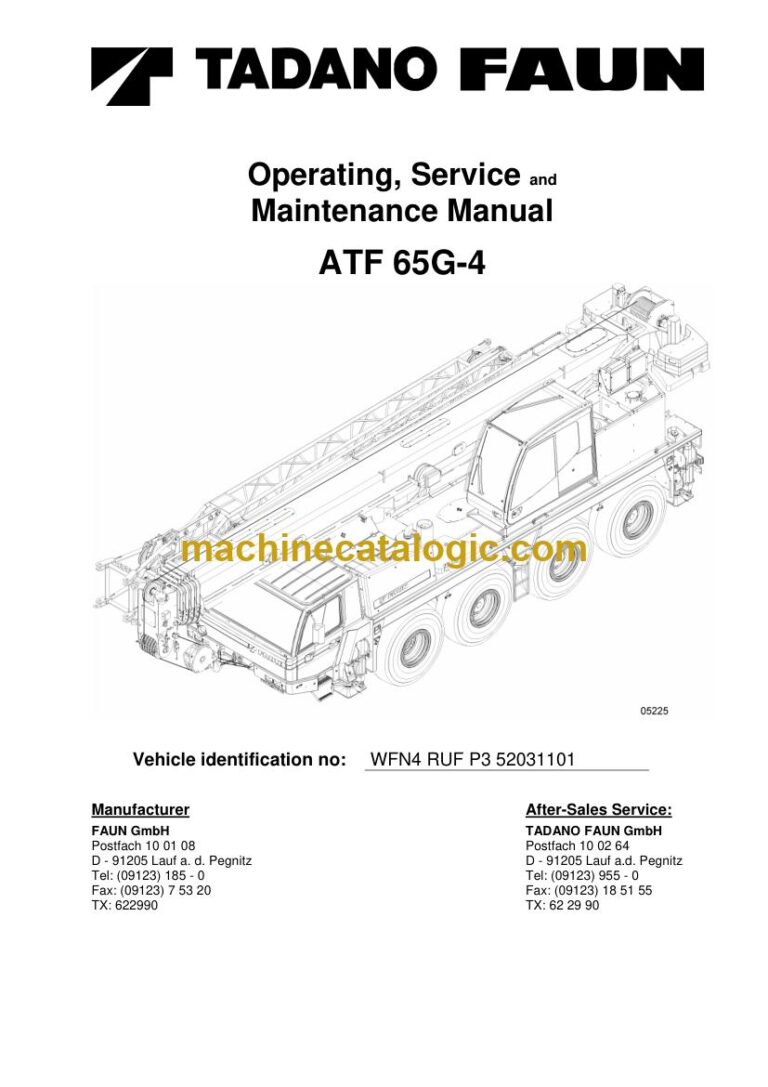
A Tadano ATF 65G-4 is a multi-axle all terrain crane. It drives to site on public roads, then sets up and lifts with its telescopic boom. A workshop taking on a used crane that arrived without any paperwork is the typical person who wants this set, because one download puts every document for the machine in front of the whole team.
What this manual set helps you do
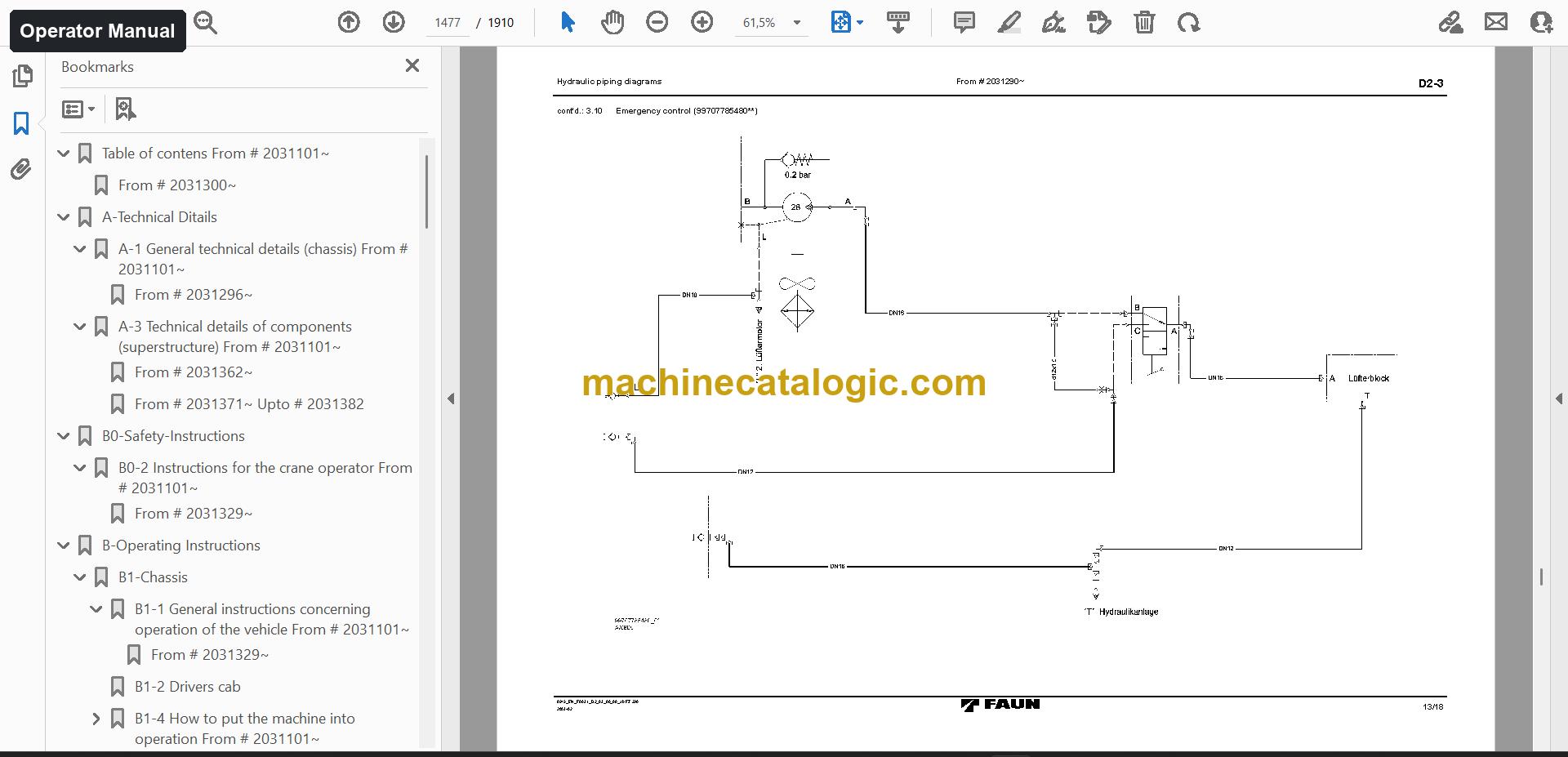
- Operate the crane correctly with the operator manual, which covers technical details, safety instructions and the requirements for road use.
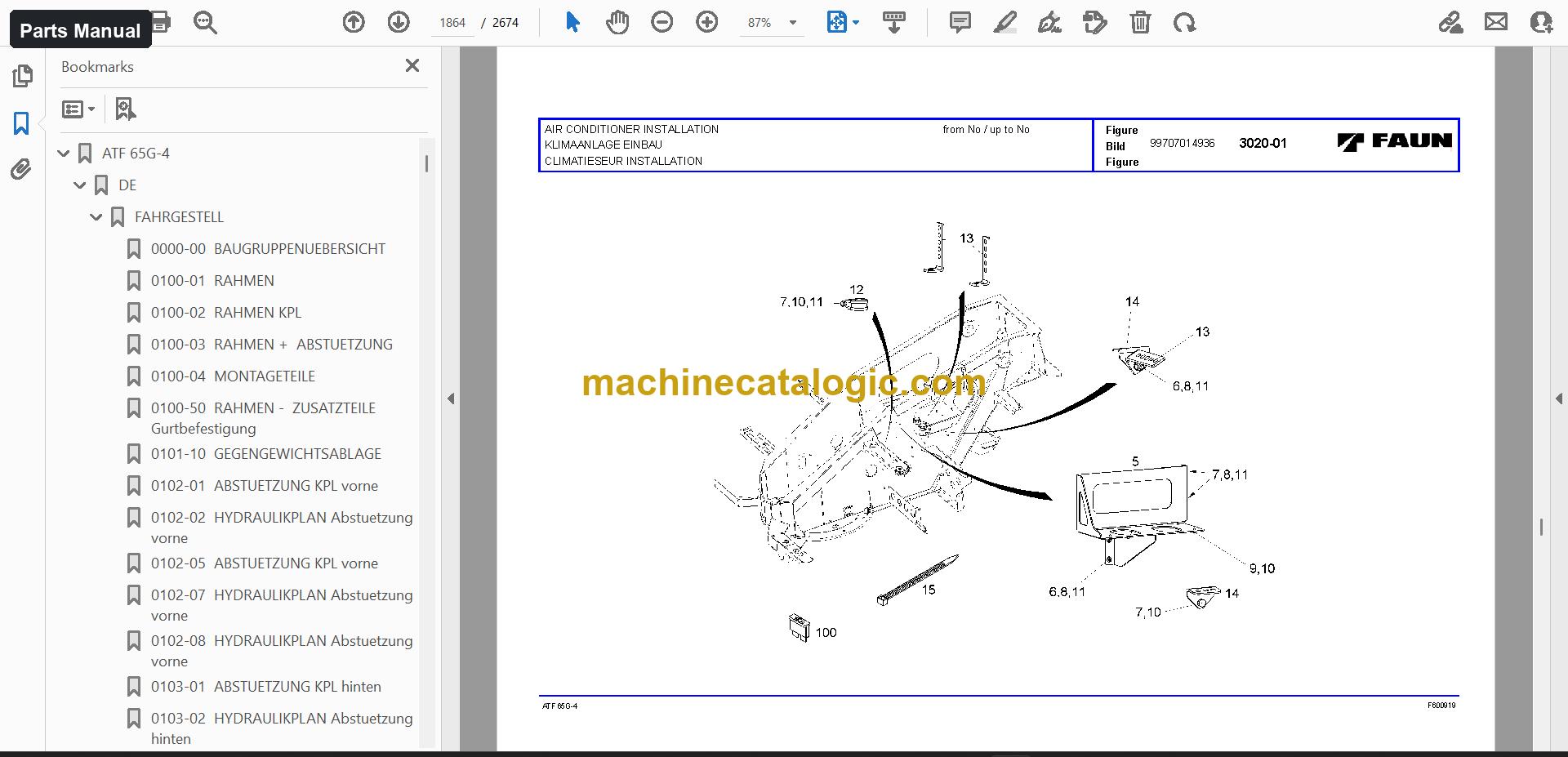
- Order the right parts with the parts manual, which has exploded views for assemblies such as drive 8×6, mirror installation and tire types.
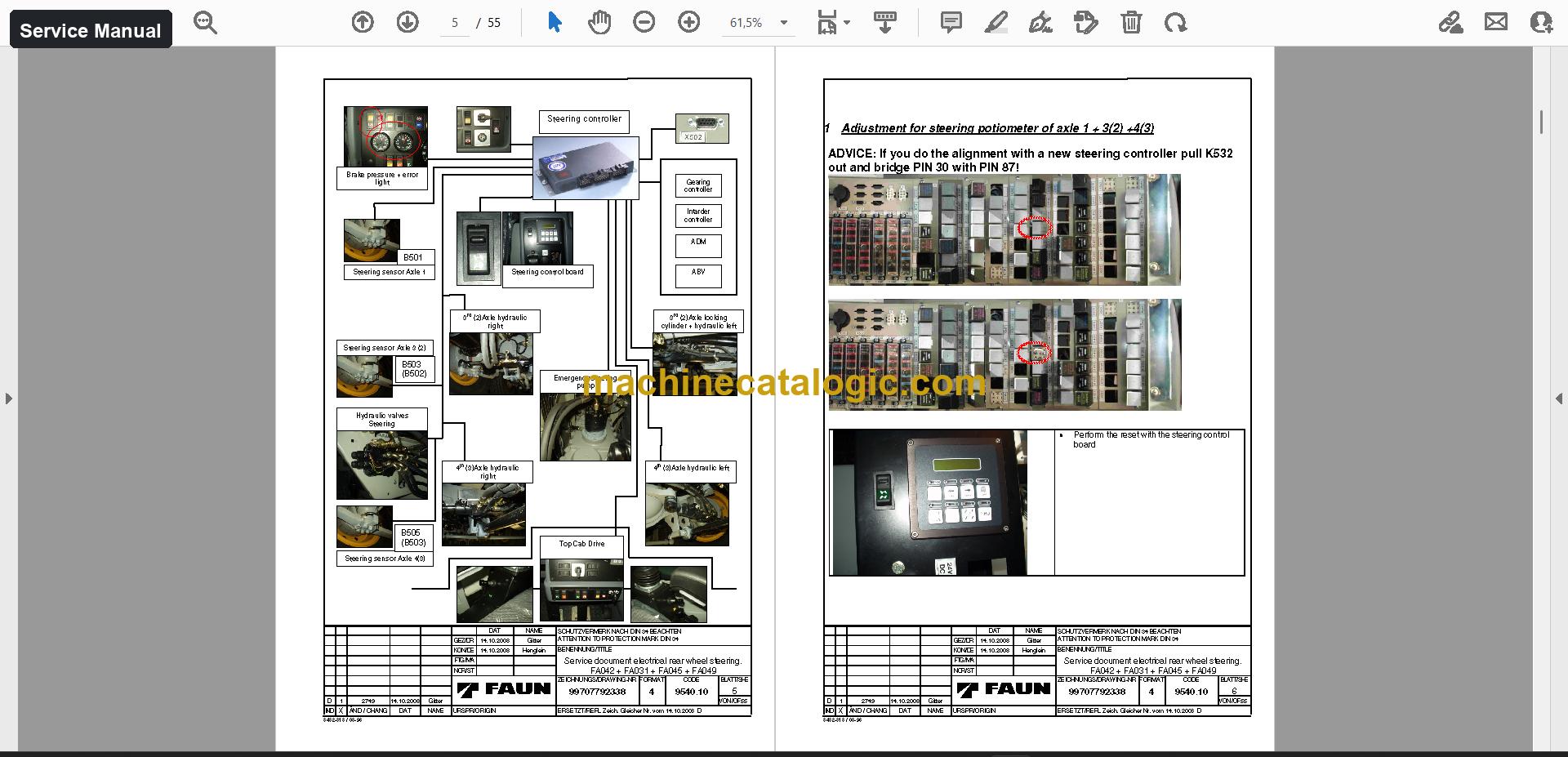
- Repair and diagnose rear wheel steering with the service manual, including reading error codes, adjusting steering potentiometers and emergency manual operation of the axles.
- Trace faults in the hydraulic and electrical systems using the schematics, 339 pages in 6 files.
- Verify the load moment limiter and run inspections using the load charts, inspection forms and the Tadano AML-B component manual.
Who this is for
Workshops and service companies that take in a used ATF 65G-4 and need to work on it without guessing. Rental fleet managers fit too, since mechanics, operators and the parts desk can all pull from the same set.
FAQ
Q: What do I receive and how is it organised?
A: You get 81 files (77 PDF) with 14,654 PDF pages in total, in English, German and French. The text can be searched and copied, so you can jump straight to an error code or a part group.
Q: Which machine does it fit?
A: It is for the Tadano ATF 65G-4. The serial number printed on the main manual cover is WFN4 RUF P3 52031101, so you can compare it with your machine's plate.
Q: How does it help with taking over a crane that has no paperwork?
A: The operator manual, parts manual, service manual and schematics sit in one place, along with technical data, training documents and diagnostic documents. Your mechanics can start on service jobs and your parts desk can start quoting right away.
Download it, open the service manual or schematics next to the crane, and you have what you need for the next job.
Does this manual fit your machine?
| Model |
Serial No. |
| ATF 65G-4 |
WFN4 RUF P3 52031101 |
The serial number shown is the one printed on the manual cover. Check the model and serial number on your machine's data plate before ordering.
📘 Show Index
Table of Contents:
Operator Manual Table of Contents
7,046 pages, 6 files
- Serial No. WFN4 RUF P3 52031101 (1,910 pages)
- A-Technical Ditails
- A-1 General technical details (chassis) From # 2031101
- A-3 Technical details of components (superstructure) From # 2031101
- B0-Safety-Instructions
- B0-2 Instructions for the crane operator From # 2031101
- B-Operating Instructions
- B1-Chassis
- B2-Superstructure
- C Service and Maintenance
- C1 chassis
- C2 Service and Maintenance Superstructure
- D-Circuit and piping diagrams
- D1 Chassis
- D2 Superstructure
- E-Crane testing instructions
- F-Troubleshooting
- F-1 Chassis
- F-2 Superstructure
- G Annex
- G-1 Chassis
- G-2 Superstructure
- Serial No. 2031101 (1,013 pages)
Same chapters as the edition above (another edition or language of this manual).
- Serial No. 2031399 (1,066 pages)
- Part A) Technical Details
- General technical details (chassis)
- Dimensions and weights
- Driving performance data (according to DIN 70020)
- Technical details of components (chassis)
- Technical details of components (superstructure)
- Engine
- Hydraulic system
- Hoisting gear
- Illustration of the vehicle
- Notes referring to the load (lifting capacity) and supporting forces charts
- Explanation regarding a load chart
- Supporting forces charts
- Part B.0) Safety Instructions
- Requirements and conditions for vehicles used in public road traffic
- Instructions for the crane operator
- Applications planning
- Steps to be taken before crane operation
- Supporting the crane by outriggers
- Instruction Sheet for Overload Safety Devices for Boom Cranes (excerpts)
- Part B) Operating Instructions – B1) Chassis
- General instructions concerning operation of the vehicle
- Warning and instruction plates
- Location of warning and instruction plates
- Components, assemblies – installation location and position
- Driver's cab
- How to put the machine into operation
- Gearshift and driving operation
- Gearbox
- Transfer box
- Brakes
- Outrigger the vehicle
- The vehicle must be lowered and The axle suspension must be locked
- Control of the electric outrigger actuation
- Outrigger operation from the chassis
- Emergency control features
- Hydraulic system
- Centering the 3rd and 4th axles
- Operation in winter
- Steps for access to the superstructure
- Attachments, optional equipment and accessories
- Instrument panel – chassis
- Part B) Operating Instructions – B2) Superstructure
- General information
- Warning and instruction plates
- Location of warning and instruction plates
- Components, assemblies – installation location and position
- Crane cabin
- Gearshift, driving and outrigger operation from the superstructure
- Changing-over to driving from the superstructure
- Starting the engine in the chassis from the superstructure
- Air brake system
- Serial No. 2031410 (1,068 pages)
Same chapters as the edition above (another edition or language of this manual).
- Serial No. WFN4 RUF P3 52031101 (1,989 pages)
Same chapters as the edition above (another edition or language of this manual).
Parts Manual Table of Contents
6,659 pages, 3 files
Service Manual Table of Contents
114 pages, 3 files
- Publication 99707792338 (111 pages)
- Adjustment for steering potiometer of axle 1 + 3(2) +4(3)
- SETUP procedures for the axles
- Read error codes
- Error Codes on the control board
- To read and erase the stored error codes via the control board
- Error Codes with WIN PCS
- Diagnosis with WIN PCS
- Start the software according chapter 2.4
- Diagnosis with the Steering control board
- Emergency manual operation to bring 3.(2) and 4.(3) axle in straight position
- Disable shifting lock by disconnecting 2-pole-plug X515
- PIN table
- CAN Bus Carrier
- Software Download
- Software description and register
- Flash connector ( Programming )
- Programming cable
- Error Codes
- User manual for steering functions
- Mounting of steering potentiometer
- Manual 2 (3 pages)
Also in this set
- Schematics (6 files, 339 pages)
- Load charts (3 files, 3 pages)
- Technical data (25 files, 48 pages)
- Service information (9 files, 22 pages)
- Assembly and installation (2 files, 8 pages)
- Diagnostic documents and software (9 files, 141 pages)
- Training documents (3 files, 26 pages)
- Inspection forms (5 files, 52 pages)
- Component manuals (4 files, 196 pages)
- General Documents
- Tadano AML-B Load Moment Indicator
- Other documents (3 files)
Tadano PDF Manuals
All Crane Manuals