$ 0
0
$ 0
0

Tadano TM-1800-1 Boom Truck Service Manual

Format: PDF (Printable Document)

File Language: English

File Pages: 594

File Size: 41.14 MB (Speed Download Link)

File Count: 4 PDF files

Brand: Tadano

Model: TM-1800-1

Equipment Type: Boom Truck

Book No: TM-1800-1-S1(U)-4E

Manuals Included: 4 separate publications

Type of Document: Service Manual

Serial No.: 655678 and up, EX0001 and up

Searchable: Partly, some files are scanned pages without a text layer

Delivery: Instant download after payment

Categories: ,

$ 55

Share:

Tadano TM-1800-1 Boom Truck Service Manual

A Tadano TM-1800-1 is a boom truck, a telescopic boom crane mounted on a truck chassis. It sets up on outriggers, lifts and places loads on a job site, then drives to the next one. When one of these comes into the shop out of warranty, the tech needs repair procedures and checks, not guesses. That's what a service manual is for.

What this manual helps you do

  • Troubleshoot the hydraulic power generating system when the crane is slow, weak or won't build pressure.
  • Rebuild or replace components in the outrigger system, swing system and boom elevating system.
  • Adjust the winch system and boom telescoping system using the data, adjustment and checks section.
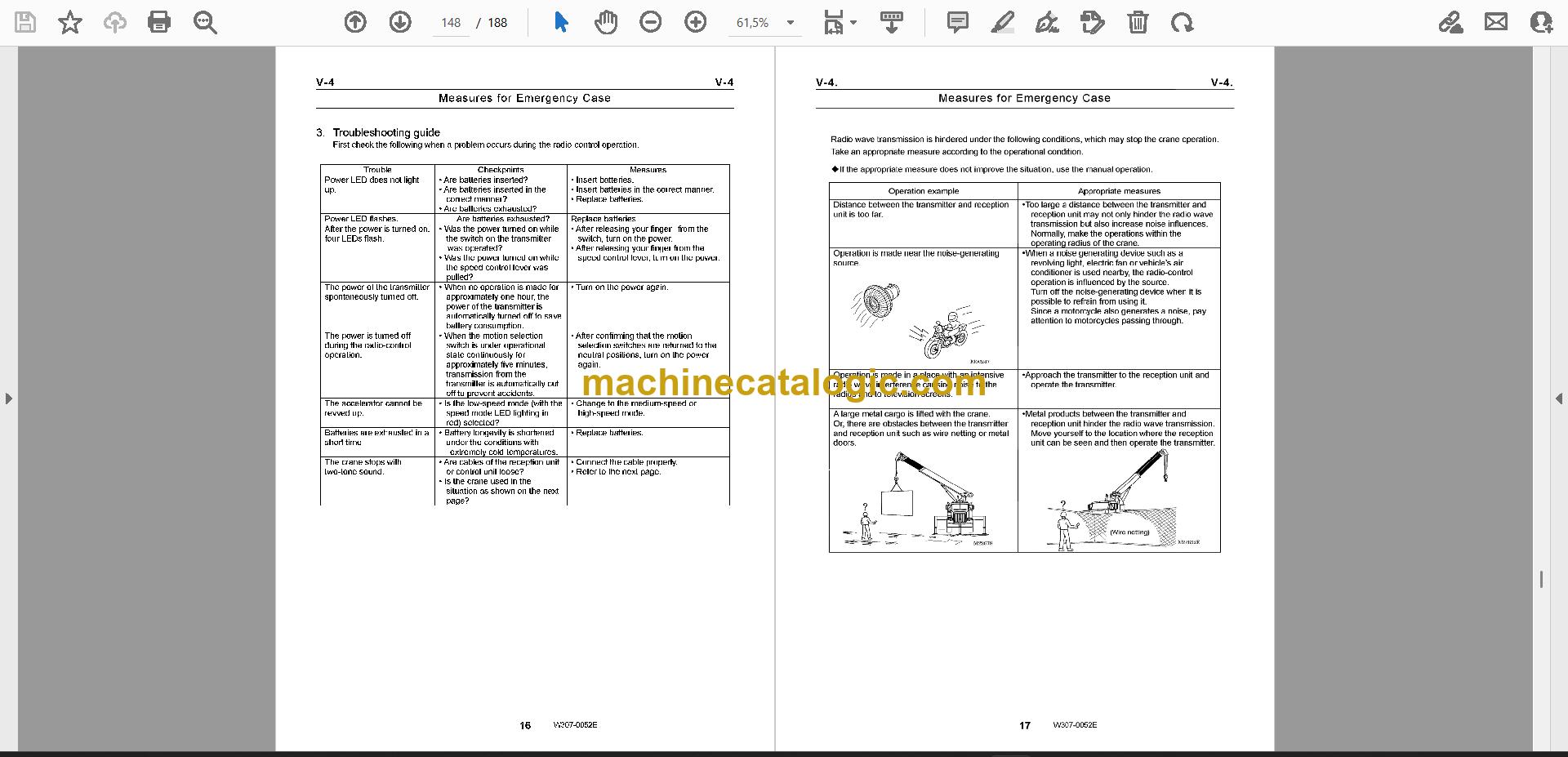
  • Verify the safety system and remote control system after repairs.
  • Trace circuits and hydraulic lines using the system diagrams.

Who this is for

Crane service technicians, rental fleet mechanics and independent repair shops working on a TM-1800-1. It also suits a shop that picked up a used crane with no paperwork and has to get it running right.

FAQ

Q: What do I receive and how is it organised?

A: You get the full set of 4 PDF files, 594 pages in total, in English. The set holds publication SA01-01-2E (58 pages), TM-1800-1-S1(U)-3E (160 pages), and two copies of TM-1800-1-S1(U)-4E (188 pages each), one of them the main manual.

Q: Which machine and serial numbers does it fit?

A: The TM-1800-1. The main manual cover reads serial number 655678 and up, EX0001 and up, under publication TM-1800-1-S1(U)-4E.

Q: How does it fit the job I'm doing?

A: A manual like this is organised by system, so you'd go straight to the section for the hydraulic power generating system, outriggers, swing, boom elevating, winch or boom telescoping. The safety, remote control, data and adjustment sections, and system diagrams, are there for testing and troubleshooting.

If you're repairing a TM-1800-1 in your own shop, this is the set to have open on the bench.

Click here to view the preview (PDF)

Does this manual fit your machine?

Model Serial No.
TM-1800-1 655678 and up, EX0001 and up

The serial number shown is the one printed on the manual cover. Check the model and serial number on your machine's data plate before ordering.

📘 Show Index

Table of Contents:

  • Publication TM-1800-1-S1(U)-4E / Serial No. 655678 and up, EX0001 and up (188 pages)
    • Safety
      • Fundamental cautions
      • Cautions in working
      • Cautions in operation
    • Foreword
      • Applicable unit No
      • Separate service manual
      • Outline of specifications
    • (B) Hydraulic Power Generating System
      • high/low shift)
      • B-2 Manual Control Valve (Outrigger)
      • B-3 Manual Control Valve (Winch)
    • (C) Outrigger System
      • C-1 Jack Cylinder (Front and rear stabilizer)
      • C-2 Jack Cylinder (Outrigger and front outrigger
      • C-3 Jack Cylinder (Outrigger and front outrigger EX0038–)
    • (D) Swing System
      • D-1 Hydraulic Motor (Swing)
      • D-2 Swing Speed Reducer
      • D-3 Swing Bearing
    • (E) Boom Elevating System
      • E-1 Boom Elevating Cylinder
      • E-2 Counterbalance Valve (Elevating)
    • (F) Winch System
      • F-1 Winch
      • F-2 Hydraulic Motor (Winch EX0044–)
      • F-3 Counterbalance Valve (Winch)
    • (G) Boom Telescoping System
      • G-1 Boom (Six-section boom)
      • G-2 Telescoping Cylinder
      • G-3 Counterbalance Valve (Telescoping)
    • (H) Safety System
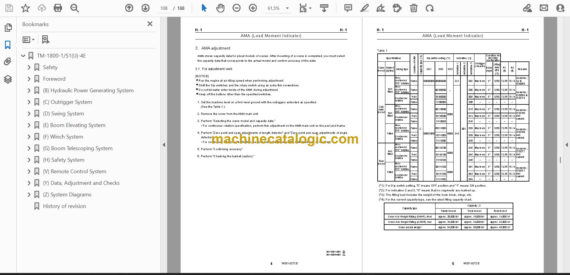
      • H-1 AMA (Load Moment Indicator)
      • H-2 Boom Length and Angle Detector
      • H-3 Outrigger Extension Detector
    • (V) Remote Control System
      • V-1 Configurations of Radio-control System
      • V-2 Radio-control Valve
      • V-3 Accelerator Cylinder
    • (Y) Data, Adjustment and Checks
      • Y-1 Service Data
    • (Z) System Diagrams
      • 515 (Radio-control spec.)
      • Manual spec.)
      • Z-6 Electric Circuit: TM-1800-1-115,215 (Continuous rotation, Manual spec.)
    • History of revision
  • Publication SA01-01-2E (58 pages)
    • Foreword
      • 1.Contents
      • 2.Conversion
    • Contents of Information
      • 1.Basic Cautions
    • Hydraulic System Troubleshooting
      • 1.Actuator malfunction
      • 2.Noise and vibration
      • 3.Oil heating
    • Dismounting and Remounting
    • Disassembly and Reassembly
      • 1.Cylinder
      • 2.Valve
    • Sealing Parts
      • 1.Packing
      • 3.Backup ring
      • 4.Seal ring
    • Piping Procedure
      • 1.How to apply seal tape
      • 2.Screwing R fittings
      • 3.Connecting high-pressure hoses
    • Machine Elements
      • 1.Bolt, nut
      • 2.Bearing
      • 3.Wire rope
    • Hydraulic Oil
      • 1.Hydraulic oil control
      • 2.Evaluating oil deterioration and contamination
      • 3.Hydraulic oil changing procedure
    • History of revision
  • Publication TM-1800-1-S1(U)-3E / Serial No. 655678 and up, EX0001 (160 pages)
    • Safety
      • Fundamental cautions
      • Cautions in working
      • Cautions in operation
    • Foreword
      • Applicable unit No
      • Separate service manual
      • Outline of specifications
    • (B) Hydraulic Power Generating System
      • B-2Manual Control Valve (Outrigger)
      • B-3Manual Control valve (Winch)
      • B-4Hydraulic Pump
    • (C) Outrigger System
      • C-1Jack Cylinder (Front & rear stabilizer)
      • C-2Jack Cylinder (Outrigger -EX0037)
      • C-3Jack Cylinder (Outrigger EX0038–)
    • (D) Swing System
      • D-1Hydraulic Motor (Swing)
      • D-2Swing Speed Reducer
      • D-3Swing Bearing
    • (E) Boom Elevating System
      • E-1Boom Elevating Cylinder
      • E-2Counterbalance Valve (Elevating)
    • (F) Winch System
      • F-1Winch (Applicable Serial No.EX0044-)
      • F-2Hydraulic Motor(Winch) (Applicable Serial No.EX0044-)
      • F-3Counterbalance Valve(Winch)
    • (G) Boom Telescoping System
      • G-1 Boom (Six-section boom)
      • G-2 Telescoping Cylinder (Six-section boom)
      • G-3 Counterbalance Valve (Telescoping)
    • (H) Safety System
      • H-1AMA (Load Moment Indicator)
      • H-2 Boom Length/Angle Detector
    • (V) Radio Control System
      • V-1Configurations of Radio-control System
      • V-2Radio-control Valve
      • V-3Acclerator Cylinder
    • (Y) Data, Adjustment and Checks
      • Y-1Service Data
    • (Z) System Diagrams
      • Manual spec.)
      • Z-6 Electric Circuit : Spec.TM-1800-1-115 (Continuous rotation, Manual spec.)
      • Z-8 Location of Hydraulic Parts
    • History of revision
  • Publication TM-1800-1-S1(U)-4E / Serial No. 655678 and up (188 pages)
    • GROUP INDEX
    • General
      • General Cautions (A) – refer to separate manual SA01-01-2E
    • Hydraulic Power Generating System
      • high/low shift)
      • Manual Control Valve (Outrigger)
      • Manual Control Valve (Winch)
    • Outrigger System
      • Jack Cylinder (Front and rear stabilizer)
      • Jack Cylinder (Outrigger and front outrigger
      • Jack Cylinder (Outrigger and front outrigger EX0038–)
    • Swing System
      • Hydraulic Motor (Swing)
      • Swing Speed Reducer
      • Swing Bearing
    • Boom Elevating System
      • Boom Elevating Cylinder
      • Counterbalance Valve (Elevating)
    • Winch System
      • Winch
      • Hydraulic Motor (Winch EX0044–)
      • Counterbalance Valve (Winch)
    • Boom Telescoping System
      • Boom (Six-section boom)
      • Telescoping Cylinder
      • Counterbalance Valve (Telescoping)
    • Safety System
      • AMA (Load Moment Indicator)
      • Boom Length and Angle Detector
      • Outrigger Extension Detector
    • Radio-control System
      • Configurations of Radio-control System
      • Radio-control Valve
      • Accelerator Cylinder
    • Data, Adjustment and Checks
      • Service Data
    • System Diagrams
      • Hydraulic Circuit
      • Electric Circuit
      • Location of Hydraulic Parts

Tadano PDF Manuals

All Crane Manuals

Related Manuals

0
0
Your Cart
Your cart is emptyReturn to Shop